German versionGerman

Universal USB-Interface-Chip

employing PIC18F2455


back to my projects , PIC-micrcontrollers , Electronic , Homepage


general Overview
Preface
Whats is USB4all
What is USB4all not
How to use
Download
known problems, some tricks ...

back to PIC-Projects
Photo USB4all-board


General Overview

Firmware update:

with Bootloader via USB
functionary
power supply:
Bus-powered (max. 100mA)

necessary external parts:
1 crystal, 4 capacitors, 1 inductor
digital IO-pins: max. 20 or 31
TTL-level, Output max 20mA functionary
ADC: 10 inputs 10 bit or 12 bit resolution
functionary
RS232: 1
300..115000 baud functionary
I2C: 1
Master-Mode, 100/400/1000 kHz
functionary
SPI:
1  (+ 6  CS)
750 kHz ... 12 MHz functionary
shift register:
1
50 Hz .. 50 kHz
functionary
Microwire-Bus: 1
750 kHz ... 12 MHz
functionary (untested)
PWM-outputs: 2
max. 10 bit resolution, 3 kHz ... 480 kHz functionary
internal memory (EEPROM):
192 byte functionary
LCD-interface: 2
dot-matrix-displays with HD44780-controller
up to 2x40 or 4x20 symbols each
functionary (2- or 4-lines)
stepper motor interface: 4 x ABCD-phases
4 Hz..10000 Hz  half-/full-step/wave (unipolar motor)
functionary

4 x L297-interface
4 Hz..1000 Hz functionary
Frequency counter:
1
Fmax = 50 MHz, 5 decimal digits, max. resolution: 10 Hz
functionary
RC-model-servos:
max. 13
100 steps
functionary
Impulse counter: 2
0 .. 65535
functionary
overview


Preface

Many modern computer mainboards or laptops don't have legacy-ports (RS232- and parallel port) anymore. Consequently the hobbyist has to switch over to the USB-port, if he wants to connect self made hardware with a computer. On a different webpage I described how to develop a USB-device, but not everybody likes to spend a lot of time in understanding the details of the USB-interface. It is much more convenient to use a ready-made USB-solution and to put this black-box into the own project, to solve all USB-problems.

Such a solution exists: the IO-warrior-chips. They are available for a fair price and simplify the development of USB-devices. But they have some weaknesses too. Because of this, I made my own universal USB-interface-chip, based on a microchip PIC18F2455 microcontroller. This chip meets my specs and I call it USB4all. It is available in two "flavors":
  • USB4all-MCD (better performance)
  • USB4all-CDC (simper to use)
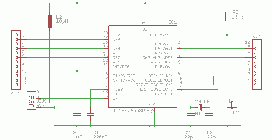
Schematic


IO-Warrior
USB4all-MCD
USB4all-CDC
Pros:
some versions don't need a crystal,
bus-powered up to 500mA,
development environment,
no driver necessary,
firmware updates via USB (boot loader) possible,
fast USB-interface,
analog inputs (10- or 12-bit-ADC),
PWM-outputs (semi analog),
output for stepper motor,
frequency counter,
internal EEPROM,
RC-servo interface,
...
firmware updates via USB (boot loader) possible,
analog inputs (10- or 12-bit-ADC),
PWM-outputs (semi analog),
output for stepper motor,
frequency counter,
internal EEPROM,
RC-servo interface,
no driver necessary,
Disadvantages
no analog interfaces,
control commands with low comfort,
some external parts necessary,
special software interface,
no development environment,
bus-powered up to 100mA,
some external parts necessary,
bus-powered up to 100mA,


What is USB4all
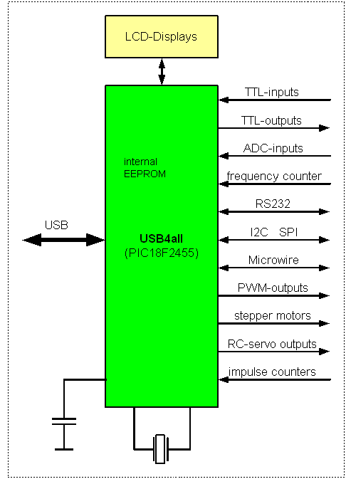
USB4all is an interface chip, made to control self made hardware via USB. It is a PIC18F2455 microcontroller (other possible types are listed below) programmed with a special free firmware.


What is USB4all not
USB4all is not a controller to build autonomous PC-independent devices. It can not directly connect peripheral equipment, connected to its many interfaces.

Example:
USB4all can measure voltages and it can control an LCD-display. But it can not display the result of the measurement on the LCD by its own.
The computer has to read out the measured voltage from the USB4all and has to write it back to the LCD via USB4all.


Which Microcontroller can be used
The firmware was developed for the PIC18F2455, but it works without modification in PIC18F2550 / 2458 / 2553 / 4455 / 4550 / 4458 / 4553. some of this chips offer more digital IO-pins or a better ADC-resolution:

ADC resolution
With PIC18F2455 /2550 /4455 /4550 the ADC has 10 bit resolution.
With PIC18F2458 /2553 /4458 /4553 the ADC has 12 bit resolution.

number of digital IO-pins
With PIC18F2455 /2550 /2458 /2553 up to20 digital IO-pins can be used.
With PIC18F4455 /4550 /4458 /4553 up to20 digital IO-pins can be used, if the 40-pin-firmware is loaded.


How to use
USB4all-MCD uses the same Microchip-driver as my bootloader and my Brenner8. The programming interface is the Microchip-DLL "mpusbapi.dll".
USB4all-CDC uses an emulated RS232-port (e.g. COM3), thus it needs no driver.

I tried to keep the user interface as simple as possible. Every control step follows this pattern:
The encoded command is made up from some bytes.

1. Byte
The 1st Byte is addressing the subsystem of USB4all for this specific command. The following subsystems exist:
2. Byte
The 2nd byte describes the kind of the command. This is in the very most cases:
For some subsystems the meaning of the byte 2 is different. For example: it makes no sense to write a string to the ADC-subsystem.

3. Byte ...
Starting with the 3d byte the data depends on the command.


Examples:

LCD-Display,  initiate the display and write the symbol "A" in the first line:
PC sends to USB4all
Meaning USB4all answers
0x55 - 0x01 - 0x00 initiate LCD with default configuration: 2-lines x 16-symbols 16 dummy-bytes
0x55 - 0x02 -'A' send 'A' 16 dummy-bytes


LCD-Display, initiate the display and write the string "Hallo Welt":
PC sends to USB4all Meaning USB4all answers
0x55 - 0x01 - 0x00
initiate LCD with default configuration: 2-lines x 16-symbols 16 dummy-bytes
0x55 - 0x02 - 0x0A - 'Hallo Welt' send  'Hallo Welt' 16 dummy-bytes


measure the voltage level at the pin AN0:
PC sends to USB4all
Meaning USB4all answers
0x51 - 0x01 - 0x01 - 0x00
initiate the ADC, select analog input AN0 by default
16 dummy-bytes
0x51 - 0x03 read the voltage level
0x51 - 0x03 - low - high
The low-byte contains the lower 8 bit of the 10-bit-result, while the high-byte contains the 2 upper bits.


Measure the temperature by an LM75 sensor chip via I2C:
PC sends to USB4all
Meaning USB4all answers
0x54 - 0x01 - 0x00 - 0x00
initiate the I2C-bus 16 dummy-bytes
0x54 - 0x05 - 0x48 - 0x02
read the temperature
0x00 - 0x05 - 0x48 - 0x02 - integer-degree - fractional degree
integer-degree: this byte contains the temperature in degrees Celsius.
fractional degree: bit 7 of this byte has the value of 0.5 degree. (read LM75 documentation)


Generate a 47-kHz-square wave signal with 50% duty cycle. (PWM 1):
PC sends to USB4all
Meaning USB4all answers
0x57 - 0x01 - 0x00
initiate PWM1 at  47 kHz, 8 Bit resolution (default) 16 dummy-bytes
0x57 - 0x02 - 0x80 - 0x00
set duty cycle to 50 %
16 dummy-bytes


Turn stepper motor 50 half-steps clock wise (right):
PC sends to USB4all
Meaning USB4all answers
0x5D - 0x01 initiate the 1st stepper motor interface 16 dummy-bytes
0x5D - 0x02 - 0x32- 0x00- 0x06- 0x00 immediately turn CW 50 half-steps with a step-rate of 1000 Hz
16 dummy-bytes


Download
An alternate PCB-Layout is the 28-pin USB-Testboard.


possible future improvements
The integrated bootloader makes firmware updates easy. New firmware versions can be flashed under Windows-OS by the Software USBoot (since V 2.0) into the USB4all. As target PIC has to be selected: PIC18F2455 (or whatever is used).
Plans for the future:


known problems, some tricks  ....

Initially a to small value of the capacitor C8 between Vdd and Vss was selected. For stable operation under all circumstances a value of 1 uF .. 10 uF should be used.

To use the I2C-interface both lines of the I2C-bus have to be connected via 1.8 Kiloohm-resistors to Vdd (+5V). (as shown here)

There is no electrical insulation between computer and USB4all. Consequently the reference voltage level (Vss) for all interfaces is ground level (GND) of the computer. If the computer is not a laptop, then Vss is connected to safety-ground.

If RC-servos are used in parallel with asynchronous stepper-motors, then stepper-motor speed is limited to 30 ... 80 Hz (instead of 1000 Hz).


Development history

10.05.2012
Firmware V10:
- support for 40-pin PICs
- support for 12-bit ADCs
- model servo control with improved linearity

23.01.2012
Firmware V9:
- receive-buffer for RS232
- Bugfix I2C read-from-slave

26.08.2011
webpage in English language:

22.08.2011
Firmware V8:
- 10 ADC-inputs (instead of 5)
- 2 new16-Bit impulse counters
- Bugfix I/O-pins at Port C

04.06.2010
Firmware V7:
- code review
- 2 additional ABCD-stepper motor interfaces
- ABCD-stepper motor interfaces improved:

03.05.2010
Firmware V6:
- Bugfix:  PWM with 1024 steps
- SPI-block transfer
- bugfix: SPI Slave-Select-wire

25.04.2010

Firmware V5:
- supports SPI, shift register, Mikrowire
- bugfixes

20.11.2009
Firmware V4: supports RC-servos

27.03.2008
Firmware V3: switched over to Microchip Framework 1.2

03.05.2007
Prototype


back to my projects , PIC-microcontrollers , Electronic , Homepage
Author: sprut
published: 22.04.2007
last change: 18.05.2012